the communication between the calling microservice and the recipient microservice happens over HTTP in a RESTful manner with JSON messages. JSON over HTTP is a common way of communicating among microservices. But another school of thought believes that is not the optimal way.
The argument is that human-readable, well-structured data interchange format is of no value when the communication happens between two systems (or microservices). This is true, since you need human-readable message formats only for troubleshooting purposes and not when your systems are running live. Instead of a text-based protocol like JSON, you can use a binary protocol like Protocol Buffers (Protobuf). It provides a way of encoding structured data in an efficient manner when communications happen among microservices.
gRPC (https://grpc.io/) is an open source remote procedure call framework (or a library), originally developed by Google. It’s the next generation of a system called Stubby, which Google has been being using internally for over a decade. gRPC achieves efficiency for communication between systems using HTTP/2 as the transport and Protocol Buffers as the interface definition language (IDL). In this chapter, we discuss how to secure communications between two microservices that happen over gRPC. If you are new to gRPC, we recommend you first go through appendix I, which covers gRPC fundamentals.
RPC stands for remote procedure call. As its name implies, RPC is a protocol whereby a program can execute a function that’s running on a remote host/computer on the network. RPC typically involves generating method stubs at the client side that make it look like a local function invocation, as the following example shows, but it’s actually remote:
Figure I.1 When communicating over RPC, the client and server both use stubs to interface with each other.
gRPC has now become the method of choice for communications that happen among microservices. This is primarily because of the performance optimizations it offers compared to other common mechanisms, such as JSON over HTTP.
gRPC performs better for microservices compared to JSON/XML over HTTP for two primary reasons:
gRPC uses Protocol Buffers, also known as Protobuf.
gRPC uses the HTTP/2 transport protocol as opposed to HTTP/1.1.
Protocol Buffers are a flexible, efficient, and automated mechanism for serializing structured data. You can think of it as JSON or XML but with the following exceptions:
Understanding HTTP/2 and its benefits over HTTP/1.x
gRPC uses HTTP/2 as its transport layer protocol. HTTP/2 provides request multiplexing and header compression, which increase its performance significantly. It also employs binary encoding of frames, which makes the data being transferred much more compact and efficient for processing.
Request/response multiplexing and its performance benefits
In a client-server communication happening over HTTP/1.x, if the client wants to make multiple requests to the server (in parallel) to improve performance, multiple TCP connections have to be used.1 This is a consequence of the HTTP/1.x delivery model, where responses are sequential. By default, HTTP/1.x requests that happen over a single TCP connection are sequential as well. However, HTTP/1.x allows a client to send multiple requests to the server on a single TCP connection, using HTTP pipelining,2 but it involves lots of complexity and has been known to cause a lot of problems. It’s therefore rarely in use; sequential requests are the default.
Regardless of whether the client application uses HTTP pipelining or not, only a single response can be sent back from the server at a given time on a single TCP connection. This can cause lots of inefficiencies, which forces applications using HTTP/1.x to use multiple TCP connections even for requesting data from a single host. Figure I.3 illustrates a scenario where HTTP pipelining is in use to make parallel requests to a server over a single TCP connection and shows the sequential nature of responses being sent back.
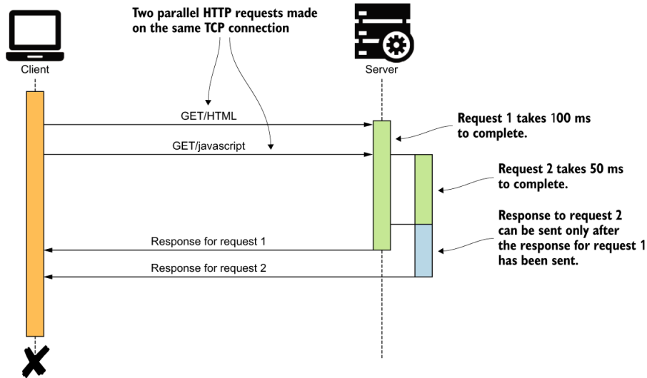
Figure I.3 A client application making two parallel requests to the server over a single TCP connection. The server processes the requests in parallel. Even though the server completes processing the second request first, it needs to wait until the response to the first request is sent before sending the response to the second request.
This problem is also known as the head-of-line blocking problem. As we mentioned earlier, this limitation has forced client applications to use multiple TCP connections in parallel. Figure I.4 illustrates how client applications work around the head-of-line blocking problem by using multiple TCP connections in parallel.
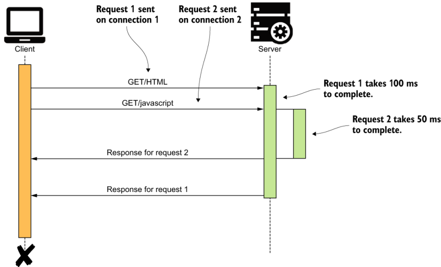
Figure I.4 A client application making two parallel requests to the server on two distinct TCP connections. The server processes the requests in parallel. Responses to requests are sent back to the client in the order of request completion.
Using multiple concurrent TCP connections may sound like the solution to the head-of-line blocking problem. However, when applied in practice, there’s a limit on the number of TCP connections that can be created between communicating parties. This is mainly due to the resource limitations including CPU, file I/O, and network bandwidth. A web browser would typically create a maximum of six concurrent TCP connections to a given host (web domain). Therefore, in the context of a web browser, the maximum level of concurrency we can achieve is six. All communications within a given single TCP connection is still sequential.
This is where request and response multiplexing in the HTTP/2 protocol becomes useful. The binary framing layer in HTTP/2 removes the aforementioned limitation in HTTP/1.x by allowing an HTTP message to be broken into individual frames, interleaved, and then reassembled on the other side. Let’s take a look at figure I.5 for a better understanding of this capability.
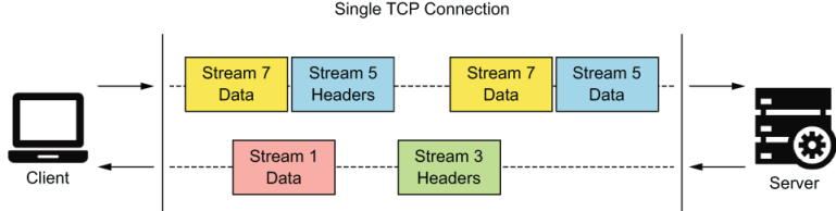
Figure I.5 A client and server communicating using the HTTP/2 protocol. The requests and responses are multiplexed over a single TCP connection so that multiple messages can be transmitted concurrently without a message having to block over another message.
As you can see, with the HTTP/2 protocol, we can transmit multiple messages concurrently. The sending party breaks each HTTP message into multiple frames of different types (DATA frames, HEADER frames, and so on) and assigns them to a stream. The receiving party reassembles the messages based on the streams and starts processing each message as soon as each message completes reassembly. This gets rid of the head-of-line blocking problem with HTTP/1.x that we discussed earlier in this section. The multiplexing capability in HTTP/2 gives us numerous benefits compared to HTTP/1.x as listed here:
Interleaving of multiple requests in parallel without blocking on any one
Interleaving of multiple responses in parallel without blocking on any one
Using a single TCP connection between client and server, which massively reduces our resource utilization and also reduces operational costs
Improving the efficiency of client applications and servers by reducing idle time waiting on one another
Avoiding underusing our network bandwidth and improving the application efficiency
Binary framing and streaming are the two fundamental concepts that allow HTTP/2 to multiplex requests and responses. Let’s take a brief look at what they are and how they have helped the HTTP/2 protocol.
Understanding binary framing and streams in HTTP/2
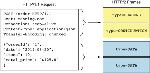
Figure I.6 An HTTP/1.x message is broken into multiple frames. The first chunk of headers is put into a frame typed HEADERS, and the consequent header chunks are put into frames typed CONTINUATION. The request body is broken into frames typed DATA.
As shown in figure I.6, an HTTP message is broken into multiple frames. Each frame has a type associated with it, which helps the receiver of the frame interpret the data in it accordingly. HTTP headers are transmitted in a frame typed HEADERS. Consequent headers of the same sequence are transmitted in a frame typed CONTINUATION. The request payload is transmitted in a frame typed DATA. A frame can hold a maximum of 16 megabytes of data. The HTTP/2 standards set the size of DATA frames to 16 kilobytes, by default, and allow the communicating parties to negotiate on higher values if necessary. When initiating a communication channel, a set of events takes place as listed here:
The client first breaks the request message into binary frames and then assigns the stream ID of the request to the frames. This way, each frame containing the binary data of the particular request gets associated with a single stream.
The client then initiates a TCP connection with the server and starts sending the frames over this connection.
Once the server receives the frames, it starts assembling them to form the request message, and then starts processing the request.
Once the server is ready to respond back to the client, the server breaks down the response into frames and assigns them the same stream ID as the request frames. Although frames can be transmitted in parallel on a single TCP connection, the stream ID in each frame allows the receiver to identify the proper message each frame belongs to. This scenario was illustrated previously in figure I.5.
The different types of RPC available in gRPC
In this section, we look at the different types of RPC available in the gRPC protocol and the types of scenarios in which each one of them become useful. These include the following:
Understanding channels
A gRPC channel represents a connection made from a client application to a host and port on a remote gRPC server. A channel has five legal states: CONNECTING, READY, TRANSIENT_FAILURE, IDLE, and SHUTDOWN.4 Each state represents a particular behavior in the connection between client and server at that moment in time. Clients can specify channel arguments, such as disabling message compression and so on, to modify gRPC’s default behavior.
What is server streaming RPC?
In the server-streaming model, the server sends a stream of responses for a single client request. Server streaming can be used when it makes sense to send multiple responses for a single client request.
Imagine a scenario in which you place an order in our retail store, and the server starts processing the order by verifying the payment and completing the shipping request. The payment processing and shipping operations can be done in two parallel microservices on the server. Through server streaming, the server now sends an update to the client as soon as each step completes. Once the server has sent all of its response messages to the client, it sends its status details (status code) and optional trailing metadata. The client uses this information to identify the end of the stream from the server.
I.4.5 What is client streaming RPC?
Similar to server streaming RPC, gRPC also supports client-streaming RPC. In this scenario, the client sends a stream of requests to the server, and the server typically (but not necessarily) sends back a single response. The server waits for the client to send its status details along with any optional trailing metadata before the server starts sending back the responses. Client streaming is useful when the client needs to submit multiple inputs to the server over a period of time before the server can perform its processing or calculations and provide the output.
Imagine that you take a metered taxi ride. The taxi (client) will upload its location data every few seconds or so. The server, upon receiving the location details, calculates the taxi fare based on the distance traveled and pushes an update to the client once every few minutes.
ave direct access unless within the application itself.
In microservices architecture, the Inventory microservice is deployed independently. Therefore, anyone with direct access to the microservice at the network level can invoke its functions. From our use case point of view, we need to prevent this. We need to ensure that the inventory is updated only upon processing an order. We therefore need to ensure that only the Order Processing microservice can execute the functions on the Inventory microservice, even if others have direct access to it. Figure 8.3 illustrates this scenario.
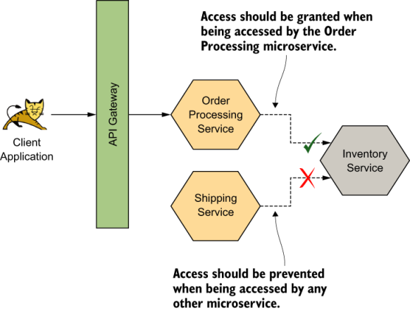
Figure 8.3 Only the Order Processing microservice should be able to access the Inventory microservice. All other accesses should be prevented
mTLS allows us to build an explicit trust between the Order Processing microservice and Inventory microservice by using certificates. Whenever a communication happens between the two parties over mTLS, the Order Processing microservice validates that it is actually talking to the Inventory microservice by using regular TLS. And the Inventory microservice validates that it is indeed the Order Processing microservice that calls it by validating the certificate of the client (Order Processing microservice).
Securing gRPC service-to-service communications with JWT
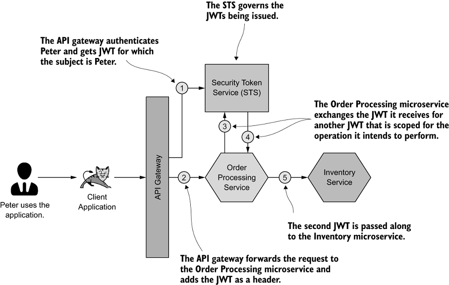
Figure 8.4 The JWT received by the Order Processing microservice is exchanged for a secondary JWT, which is scoped to access the relevant operations on the Inventory microservice.
As shown in figure 8.4, we have the Order Processing microservice, which exchanges the JWT it receives from the client application for another (second) JWT with the help of an STS. This new JWT will then be passed along to the Inventory microservice.
Unlike in HTTP, gRPC doesn’t have headers. gRPC supports sending metadata between client and server. The metadata is a key-value pair map; the key is a string, and the value can be a string or in binary form.
Summary
In a microservices deployment, given that many interactions happen over the network among microservices, JSON over HTTP/1.1 is not efficient enough.
gRPC operates over HTTP/2, which is significantly more efficient than HTTP/1.1 because of request response multiplexing, binary encoding, and header compression.
Unlike in HTTP/1.1, HTTP/2 supports bidirectional streaming, which is beneficial in microservice architectures.
gRPC supports mTLS, which you can use to secure communication channels among microservices.
mTLS does not necessarily address the full spectrum of security we need to ensure on microservice architectures; we therefore need to resort to JWTs in certain cases.
Unlike HTTP, gRPC does not have a concept of headers, so we have to use metadata fields in gRPC to send JWTs.
The client interceptors and server interceptors available in gRPC help to send JWTs from clients to servers and to validate them.


